We design and fabricate conveying systems for industrial fluids, adapting each solution to the operating conditions, the process characteristics and the installation requirements. We integrate engineering, fabrication and specialized technologies to ensure reliable performance throughout their service life.
We select the most suitable construction solution for each conveying system, incorporating technologies such as FRP, dual laminate and engineering thermoplastics when the process conditions require it.
Variables that define a conveying system
Each variable determines a specific design, fabrication or installation decision. Operating ranges and service life are defined for the specific medium, its concentration and the actual operating regime.
Type of service: gases or liquids
Determines the governing design criterion and the support strategy of the system.
Medium and concentration
Determines the resin and the veil of the internal chemical barrier.
Temperature and condensation
Determines the barrier system and the zones where attack concentrates.
Positive pressure or vacuum
Determines thicknesses and stiffening rings. A duct operating under vacuum is designed for collapse, not only for pressure.
Abrasion and suspended solids
Determines the protection of the barrier and the zones of greatest wear: elbows, reducers and direction changes.
Diameter, routing and thermal expansion
Determines the breakdown into runs, the location of joints and the design of supports and anchors.
Joints and connections
Determines whether the system is solved with flanges, field-laminated joints or a combination, and how much work remains at the site.
Installation and maintenance
Determines the prefabrication into spools, the installation sequence and the possibility of servicing one run without shutting down the whole system.
Visual record
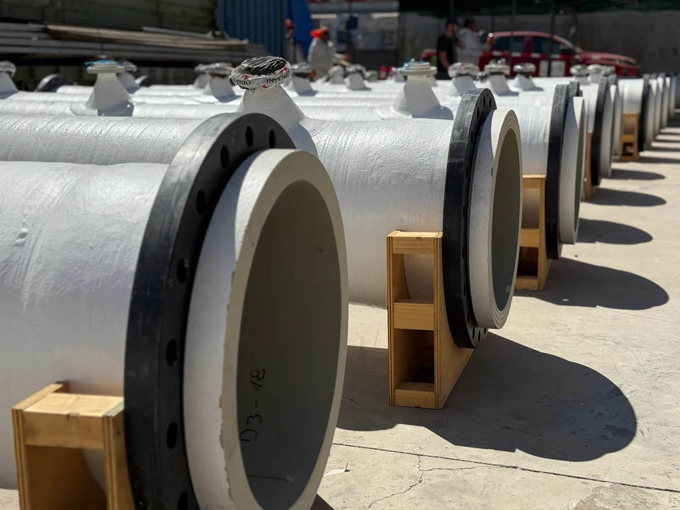
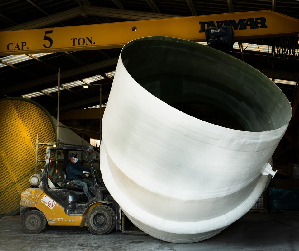
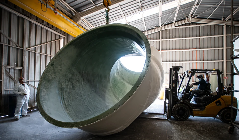
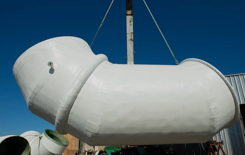
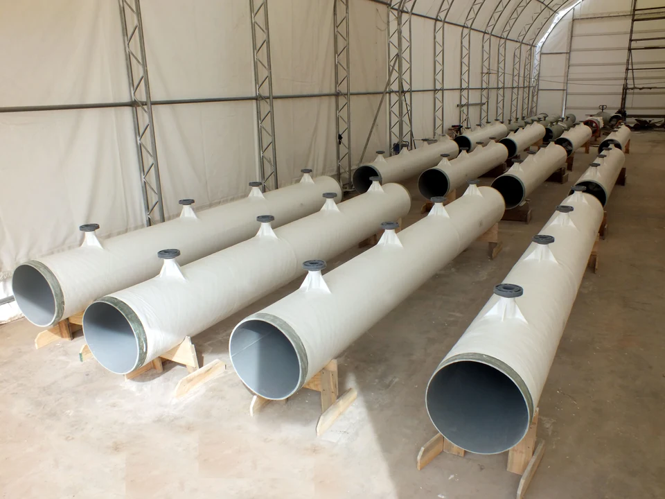
Ducts and components fabricated in FRP, and runs prepared for transport to the site.
Enlarge imageClose image
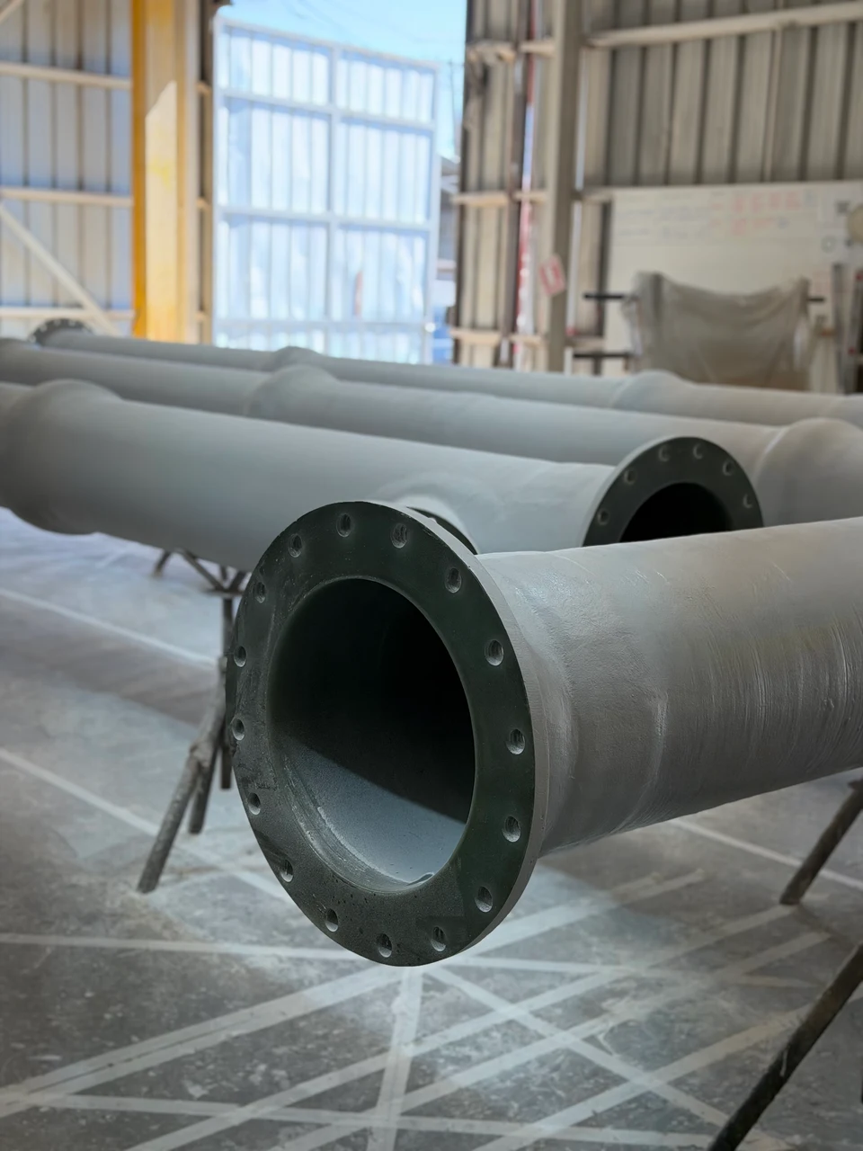
Flanged FRP spools, prepared for dispatch.
Flanged FRP spools, prepared for dispatch.Enlarge imageClose image
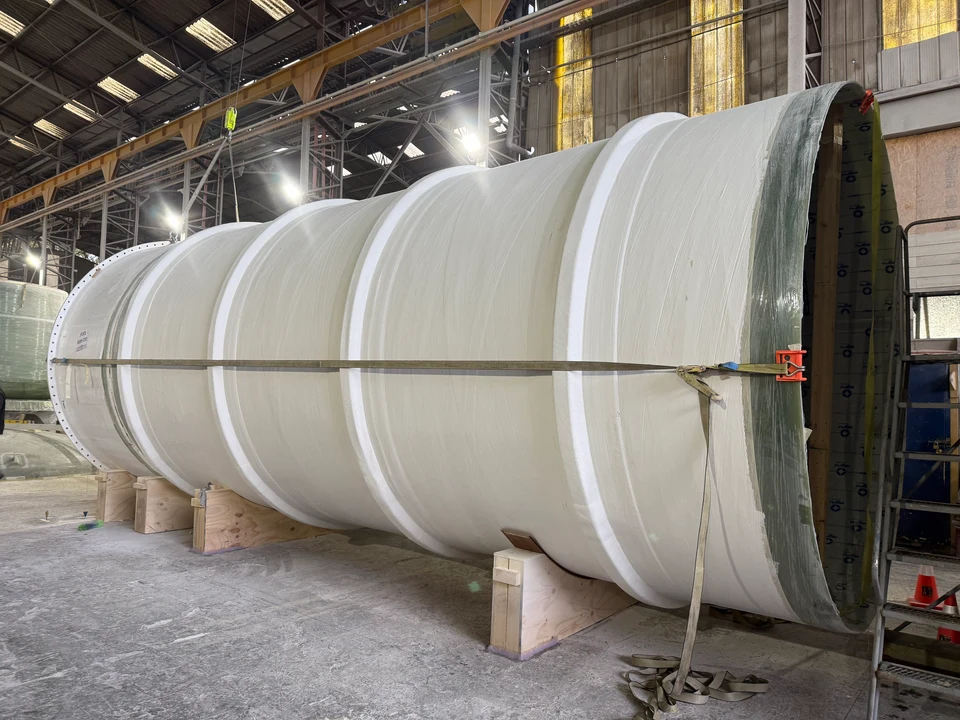
Move of a large-diameter shell course inside the workshop.
Move of a large-diameter shell course inside the workshop.Enlarge imageClose image
Special FRP equipment during its move inside the plant.
Special FRP equipment during its move inside the plant.Enlarge imageClose image
Large-diameter FRP piping elbow during its lifting.
Large-diameter FRP piping elbow during its lifting.Enlarge imageClose image
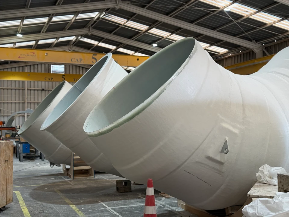
FRP piping elbows in the workshop.
FRP piping elbows in the workshop.Enlarge imageClose image
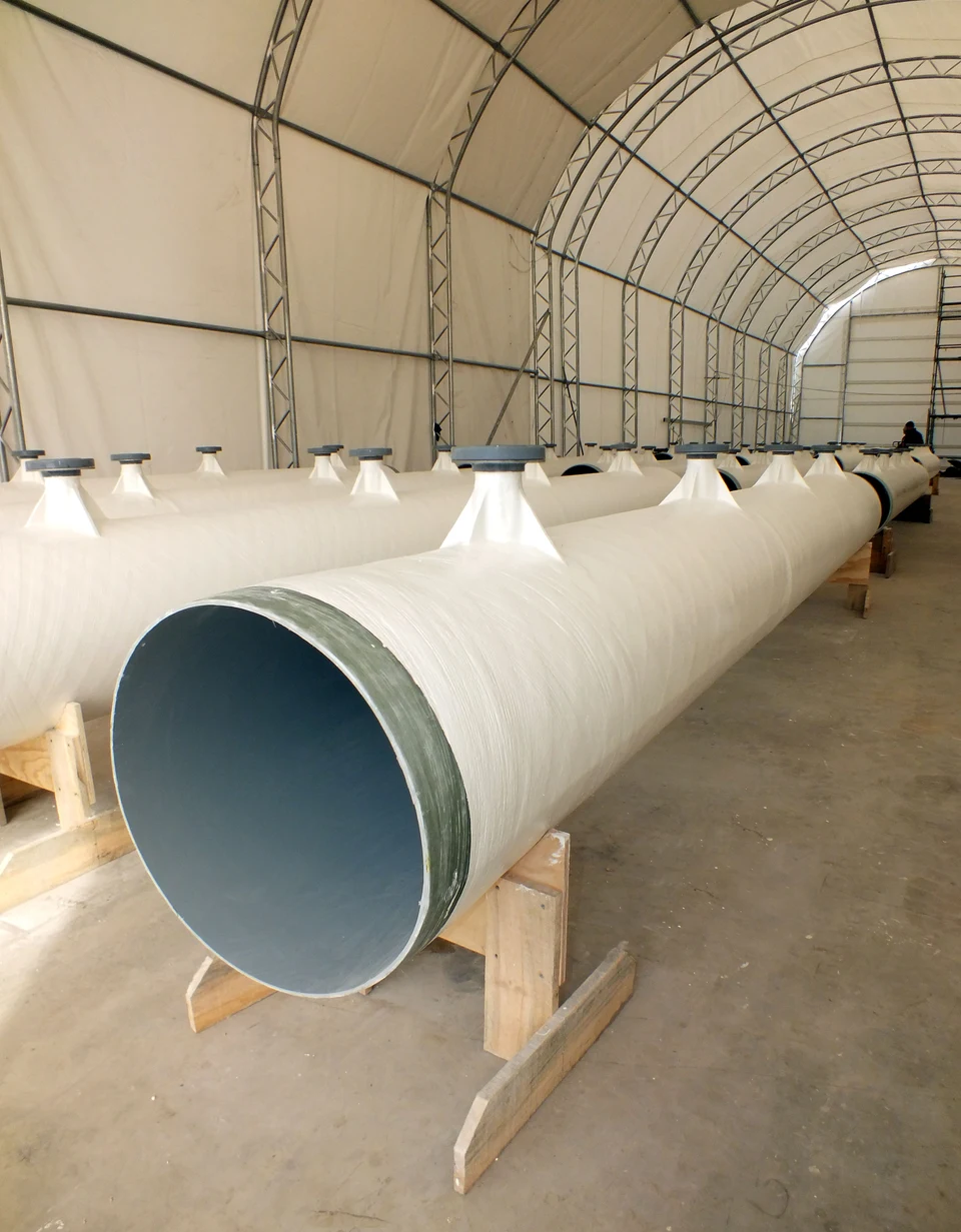
Large-diameter dual-laminate duct, operating under negative pressure.
Large-diameter dual-laminate duct, operating under negative pressure.Enlarge imageClose image
Long industrial duct made of FRP.
Long industrial duct made of FRP.Enlarge imageClose image
FRP duct sections prepared for transport and field installation.
FRP duct sections prepared for transport and field installation.Enlarge imageClose image
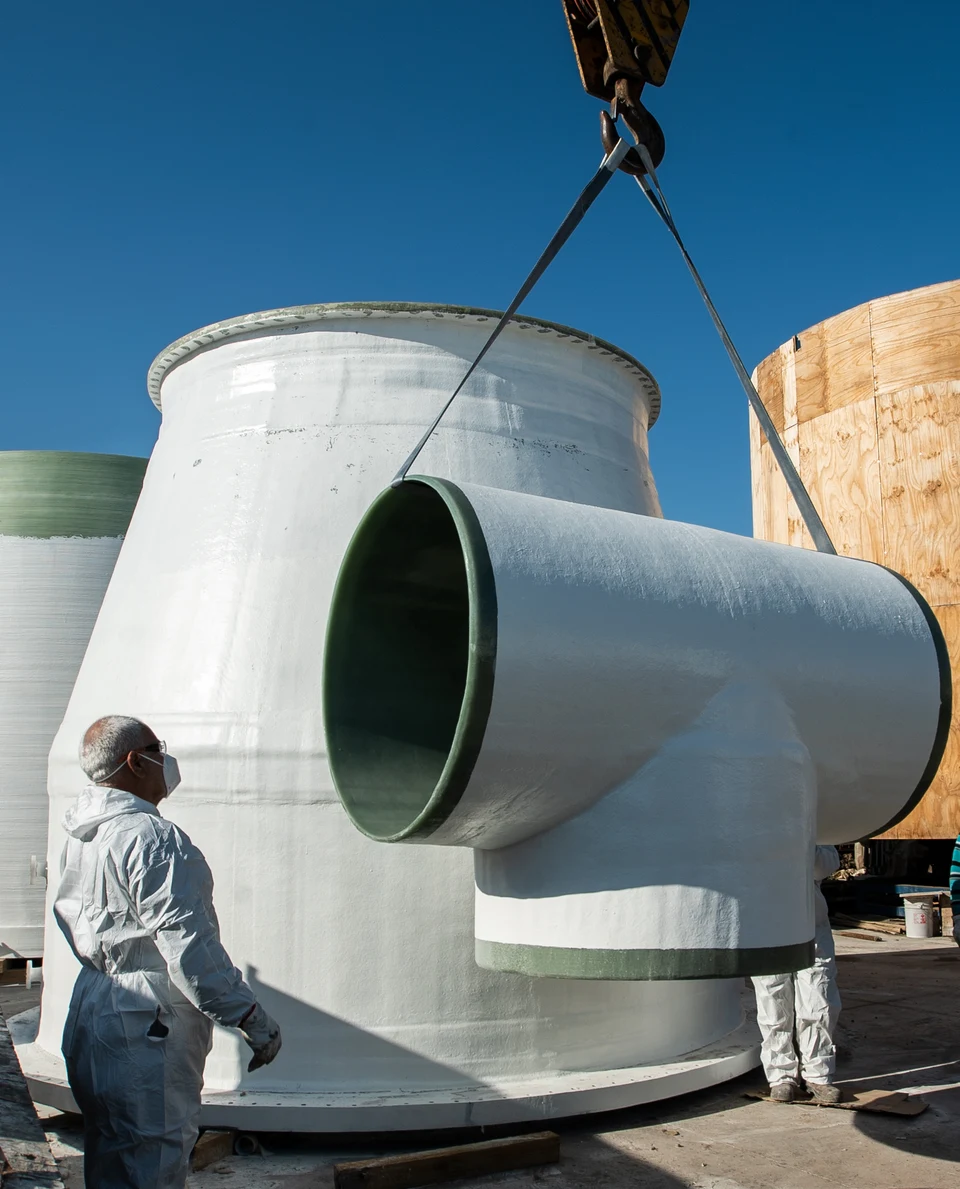
Large-diameter FRP tee during a lifting maneuver.
Large-diameter FRP tee during a lifting maneuver.Enlarge imageClose image
Do you have a conveying system to define or a damaged run?
Send the medium, the physical state, the concentration, the temperature, the pressure or vacuum regime, the diameter, the routing, the existing supports and the available window.